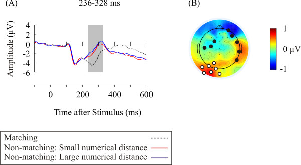
Figure 2.
The numerical distance effect. (A) ERPs averaged across representative electrodes over posterior sites (Electrode 31, 32, 33, 35, 36, 37, 39) showing the numerical distance effect. Shaded area represents the time interval showing the numerical distance effect. (B) Topographic distribution of difference ERPs (large numerical distance condition minus small numerical distance condition) during the time interval showing the numerical distance effect. Marked dots in the topographic map represent the locations of electrodes showing the numerical distance effect. Representative electrodes are marked as white while other electrodes are marked as black.

