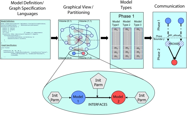
Figure 1.
Architectural overview of the Model Graph Simulator. Two languages (left) define model state and interfaces (“model definition language,” MDL), and specify graph composition and connections (“graph specification language,” GSL). The specified graph is initialized and partitioned (left center). In the case of the Neural Tissue Simulator, partitioning is according to a tissue volume decomposition. Relationships between models through interfaces define connections (expanded view) and are parameterized separately from the models themselves. Models are initialized together in memory and computed by phase and by model type (right center). Communication between models (right) occurs at phase boundaries and is achieved when state from models is marshaled, communicated, then demarshaled into model proxies. Model proxies connect locally to downstream nodes to complete the connection.

