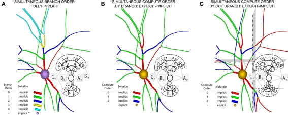
Figure 6.
Creation of our numerical approach. (A) Different branch orders may be computed in parallel across the entire neuronal arbor (represented by different colors). All junction are computed implicitly. Inset shows various matrices An–Dn representing the portion of the neuronal arbor that must be solved in a single phase (i.e., whole branch orders). Subscripts label branches indicating all branches of an order may be solved in parallel, and dotted lines also demarcate branches of an order. (B) By introducing the concept of compute orders, we introduce explicit junctions at a fixed branch order interval (in this case, determined by a maximum compute order of 2). This allows different branch orders to be computed in parallel (e.g., 0 and 3). Colors, matrices, subscripts, and dotted lines as in (A,C) By slicing the neuron tissue, additional explicit and implicit junctions are introduced at cut points, and all distal compute orders are incremented. The numerics of distal junction may also change. Colors, matrices, subscripts, and dotted lines as in (A).

