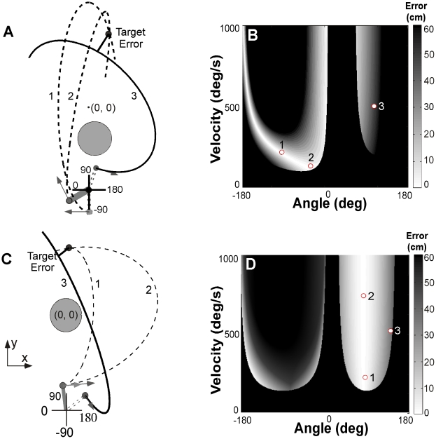
Figure 1. Workspace, execution space and solution manifold.
A: Workspace with the position of the center post and target skittle in Experiment 1. Two ball trajectories exemplify how different release variables can lead to the same result with zero error (trajectory 1, 2, dashed lines). Trajectory 3 shows a trajectory with non-zero error. B: Workspace with center post and target as used in Experiment 2. Three select trajectories exemplify the redundancy of solutions as in panel A. C: Execution space and solution manifold of target and center post configuration in Experiment 1. White denotes zero-error solutions, increasing error is shown by increasingly darker grey shades, black denotes a post hit. The release variables of trajectory 1 and 2 correspond to points 1 and 2 on the solution manifold, the variables of trajectory 3 correspond to the point 3 in a grey-shaded area (error = 30cm). D: Corresponding execution space and solution manifold. The three points correspond to the three trajectories of panel B.

