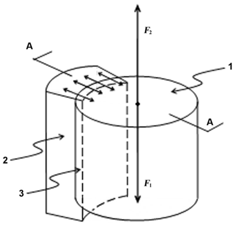
Figure 2.

Schematic of implantation of stem’s shaft in medullary canal of a cortical tube bone. 1 = shaft of stem, 2 = cortical wall of bone, 3 = endosteum removed by boring medullary canal prior to installation, A-A = cross-section, F1 = vertical load to shaft, F2 = reaction from bone walls.
