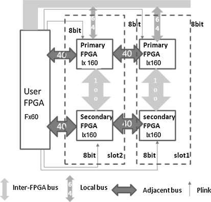
Fig. 2.
Block diagram of multiple-FPGA system. The system includes four FPGA devices (XC4VLX160) which are responsible for aggregating multiple pixels from the input images, mimicking a feed-forward model. A multi-FPGA system in which virtual connections form a two-dimensional array of receptors onto a set of neurons on a multiple-chip system mimic the feed-forward visual cortex. The host machine talks to the board through a local bus. The primary FPGA and secondary FPGA are application FPGA (XC4VLX160). The 40bit adjacent bus transfers signals into the neighboring chip if the spikes are generated. The high bandwidth bus with 100 bits at 200 MHz is used as inter-chip transmission

