
Figure 3.
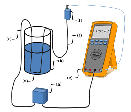
Set-up for testing of leakage current. The ICP sensor (a) was placed in a container (b) containing 0.9% NaCl solution. A metal rod (c) was placed in the 0.9% NaCl solution and connected to one side of a 500V source (h). All pins of the ICP sensor connector (f) were connected to the Volts input of the digital multimeter (g) and the multimeter Common input was connected to the other side of the 500V source. The multimeter's input impedance of 10 MΩ thus acted as a shunt resistor providing a current scale of 100pA/mV.