Abstract
Actomyosin bundles frequently form through aggregation of membrane-bound myosin clusters. One such example is the formation of the contractile ring in fission yeast from a broad band of cortical nodes. Nodes are macromolecular complexes containing several dozens of myosin-II molecules and a few formin dimers. The condensation of a broad band of nodes into the contractile ring has been previously described by a search, capture, pull and release (SCPR) model. In SCPR, a random search process mediated by actin filaments nucleated by formins leads to transient actomyosin connections among nodes that pull one another into a ring. The SCPR model reproduces the transport of nodes over long distances and predicts observed clump-formation instabilities in mutants. However, the model does not generate transient linear elements and meshwork structures as observed in some wild-type and mutant cells during ring assembly. As a minimal model of node alignment, we added short-range aligning forces to the SCPR model representing currently unresolved mechanisms that may involve structural components, cross-linking and bundling proteins. We studied the effect of the local node alignment mechanism on ring formation numerically. We varied the new parameters and found viable rings for a realistic range of values. Morphologically, transient structures that form during ring assembly resemble those observed in experiments with wild-type and cdc25-22 cells. Our work supports a hierarchical process of ring self-organization involving components drawn together from distant parts of the cell followed by progressive stabilization.
1. Introduction
Recent work in the area of cytoskeletal dynamics has examined the general physical properties of systems consisting of mixtures of motors and filaments [1-10]. Cooperativity among cytoskeletal components is essential for the formation of structures at the cell scale. Theoretical work, formulated at various levels of coarse-graining, has shown how nonlinear interactions among the motor and filament components can give rise to patterns such as bundles, stars, waves and contractile networks [1-10]. These studies have provided insights into how cells organize their cytoskeleton to form subcellular structures such as stress fibers [11, 12], contractile rings [13-15], and mitotic spindles [16, 17].
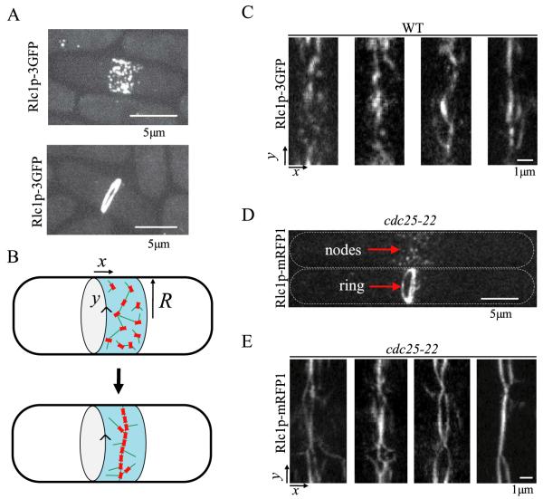
In this paper, we consider the kinetics of self-assembly of the actomyosin contractile ring during mitosis in fission yeast [18-20]. Fission yeast is a model organism that is an ideal system for the development of theoretical models of cytoskeletal dynamics for comparison with experiments [21]. The formation of the contractile ring in fission yeast involves the coalescence of a broad band of ~65 cortical nodes, see figure 1(A) [14, 22, 23]. Nodes are macromolecular structures that contain myosin-II Myo2p, actin filament nucleator formin Cdc12p, and anilin-like protein Mid1p [23-25]. Prior to the onset of condensation, the nodes are distributed in an equatorial band of width 1.8 μm. During the process of condensation that lasts about 10 min, the nodes execute a biased random walk toward the middle of the broad band [14]. In the ‘search, capture, pull and release’ (SCPR) model [14], actomyosin connections among nodes are established by actin filaments nucleated at the nodes (see figure 1(B)). Myosin at the nodes generates pulling forces; actin filament severing (likely via cofilin) generates actin turnover. Using parameter values from experiments, this model predicts ring assembly over a time consistent with experimental observations. For sets of parameter values different from those measured in experiments, such as slow actin polymerization, the model predicts clump instabilities [14, 26] as observed in Cdc12p mutants [27].
Figure 1.
Images of fission yeast cells in the process of contractile ring formation from a condensing band of cortical nodes. Transient linear elements form during the condensation process. (A) Dividing wild-type cells expressing myosin light chain Rlc1-3GFP, z-projections of confocal microscopy slices [14]. Top: a cell at early stages of the condensation process shows nodes distributed in a broad band. The nodes are macromolecular complexes bound to the inner part of the cell membrane. Bottom: a cell with a contractile ring at the end of node condensation (a process that lasts ≈10 min). The ring subsequently constricts. (B) Cartoon of ring formation with the x-axis parallel to the long axis of the cell; y measures arc length along the cell circumference. In the SCPR model, nodes condense into rings through connections established by actin filaments (green). (C) Images showing examples of wild-type cells expressing Rlc1p-3GFP during the process of ring formation. Transient linear structures are seen, in addition to isolated nodes. The images are ‘radial projections’ obtained by projecting the intensity of a hollow tube aligned along the axis of the cell onto a surface of radius R = 1.73 μm representing the cell surface. In this projection the x and y directions are those illustrated in panel B. The projection was obtained using 26 z-slices, separated by 0.2 μm. (D) z-projections of cdc25-22 cells expressing Rlc1p-mRFP1 [14]. cdc25-22 cells grow longer and accumulate more nodes in a wider band compared to wild-type cells during arrest from entering mitosis. After release into mitosis, nodes condense to contractile rings [23]. Top: cell with nodes; bottom: cell with ring. (E) Radial projection of four representative cdc25-22 cells in the process of ring assembly (obtained by 24 z-slices separated by 0.3 μm). Long linear structures are more evident compared to wild-type cells. These linear elements extend along many directions, forming meshworks. Near the end of ring assembly, parallel bundles resembling ‘two rings’ appear. In some cells, those bundles that form a ring around the cell constrict independently of the other parts of the bundle structure.
We will address a morphological feature of condensing broad bands of nodes that is not captured by the SCPR model. In images of cells expressing node marker Rlc1p-3GFP (a myosin light chain), linear transient structures are frequently observed, see figure 1(C). Such linear structures are not seen in simulations of the SCPR model. These linear structures are even more pronounced during condensation of the broad band of nodes in cdc25-22 cells expressing Rlc1p-mRFP1 after release from arrest, see figures 1(D) and (E). cdc25-22 cells develop a broad band of about 100 nodes distributed over ~3.2 μm [14]. In those cells, nodes collapse into elongated linear structures that form a dynamic meshwork structure. In some cells two partially merged parallel bundles form that appear as two rings.
The way in which the transient linear structures seen in figure 1 form remains unknown. Nodes contain about 55 Myo2p molecules which may assemble into bipolar minifilaments (though no evidence for minifilament formation in nodes exists yet) [23, 25, 28]. It is conceivable that transient binding of myosin heads to actin filaments that connect the nodes helps align the nodes into linear structures. Actin cross-linker proteins fimbrin Fim1p and α-actinin Ain1p could also be involved in node alignment [29-31]. Fimbrin can bundle actin filaments into tight bundles while α-actinin cross-links actin filaments more loosely. They both play a role during fission yeast contractile ring formation and deletions of their genes are synthetically lethal [29-31]. However their precise mechanistic role remains unclear. Another candidate molecule for node alignment is IQGAP Rng2p. This node component protein can bundle actin filaments [32]. Finally, Mid1p could also play a role through oligomerization [33].
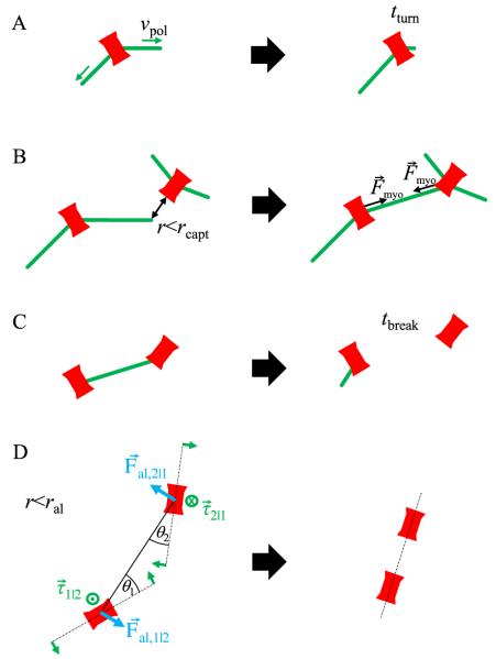
In the following sections we study a simple model for the formation of these linear elements that is an extension of SCPR. We keep the basic processes of SCPR but we add a local alignment mechanism. In this new model, nodes have a preferred axis of polarization. They align along the same direction when in close proximity (see figure 2). This node alignment process is a coarse-grained representation of all the factors that contribute to the formation of linear node structures. We examine the results of this simple combination of long-range transport of nodes through search and capture with a local alignment. We find the range of parameters for which this mechanism promotes ring stability. We further describe how the model can generate condensing broad bands that have morphological features similar to those seen in experiments.
Figure 2.
The search, capture, pull, and release model with the addition of local node alignment. Nodes are drawn as bars to illustrate their assumed polarization. (A) Search: two actin filaments grow out of each node along randomly chosen directions with rate vpol. The average lifetime of actin filaments is tturn. Filaments start to grow along a new direction after breakage. (B) Capture and pull: when an actin filament tip approaches another node, a connection is established. Connected nodes move toward one another by pulling force Fmyo. (C) Release: the average lifetime of a connection is tbreak. After breakage, filaments start growing along a random direction as in panel A. (D) Local node alignment: nodes within ral of one another experience a torque τ that rotates them to point toward one another. Additionally, the force Fal acts on node centers, perpendicularly to the line that joins two nodes. We note that even though nodes are drawn as elongated objects, the shape of the nodes is not taken into account explicitly: for example, we did not consider anisotropic friction coefficients.
2. Model
In this section we describe how the SCPR model of [14] was modified to include local node alignment. We also provide the numerical values of the parameters used in the Monte Carlo simulations. We assume that each node has an internal polarization represented by the orientation of a line element (see figure 2(A)). Nodes are assumed to be bipolar, i.e. we do not distinguish between the two poles of the node. While a monopolar structure cannot be excluded, a bipolar orientation is a reasonable starting assumption. Recent measurements in [25] indicated that the tails of Myo2p in the nodes are oriented at 71° with respect to the plasma membrane. Since myosin tails generally associate with one another, this would be consistent with an internal organization with a preferred axis. It remains unknown whether Myo2p assembles into bipolar minifilaments in nodes as in other sarcomeric-like structures.
2.1. Initial node distribution
In the simulations, nodes are objects constrained to move on a 2D plane that represents the cell membrane. The x-axis is the direction along the long axis of the cell and the y-axis is along the cell circumference (see figure 1). Periodic boundary conditions were applied at y = 2π R, where R = 1.73 μm [28]. The nodes were initially distributed along the x-axis according to a Gaussian distribution of standard deviation 0.9 μm equal to the half-width of the node distribution determined experimentally [14]. Nodes were placed according to a uniform probability distribution along the y-axis. The initial node orientation was random.
2.2. Search, capture, pull and release
We used the SCPR mechanism [14] to simulate how nodes make random connections to pull one another over long distances. None of the processes in this subsection depend on node polarization.
Search (figure 2(A))
We assume that each node polymerizes two actin filaments (represented as growing lines) along random directions on the 2D plane, as expected from the presence of two formin Cdc12p dimers per node [24, 28]. Formins polymerize actin monomers while remaining attached to the barbed end [34, 35]. We assume that the barbed end of the actin filament resides on the node while the pointed end extends out of the node as node-associated Cdc12p elongates the filament by polymerization. The filament length increases with constant speed vpol = 0.2 μm s−1 [14]. During elongation, the orientation of actin filaments remains fixed. More recent evidence suggests that Cdc12p is very dynamic in the nodes with a half-time of 30 s and may be distributed to only 50% of the myosin nodes [24]. Here, we assume that all nodes are able to nucleate actin filaments to compare with previous simulations. Ring assembly by SCPR is not sensitive to the fraction of nodes nucleating actin, as long as this fraction exceeds 50% [14].
Actin filament turnover through cofilin severing is represented by filament disappearance and regrowth along a new direction out of the node. The filament lifetime was tturn = 20 s [14]. Turnover is simulated by filament disappearance with probability dt/tturn per time step dt.
Capture and pull (figure 2(B))
When the pointed end of a polymerizing filament comes within distance r < rcapt = 0.2 μm of another node, we assume that a connection is established and pulling forces are exerted between nodes. This simulates the process of myosin heads in the target node binding to the growing actin filament and exerting a pulling force toward the barbed end at the nucleating node. The magnitude of the force is Fmyo = 4 pN, acting on each node in the direction of the other node. This force contributes to the total force shown in equation (4) below. Once a filament is captured, filament elongation is terminated [14].
Here, rcapt is two times larger than in [14], accounting for actin filament pointed end deflection due to thermal fluctuations (about 0.15 μm for a filament of length 1 μm and persistence length 10 μm [36-38]). We do not allow for capture when nodes are within 0.4 μm of one another (the distance at which the alignment mechanism is assumed to take over, see below). The combination of these two changes does not lead to significant modifications of the SCPR kinetics, see figure S15 in [14].
Release (figure 2(C))
We assume that connected filaments turn over, similarly to unconnected filaments, with lifetime tbreak = tturn = 20 s. In the simulations, each connection breaks with probability dt/tbreak per time step dt. Upon filament breakage, a new filament starts to grow along a new, randomly chosen direction.
2.3. Model of local node alignment
We added additional forces to the SCPR model to simulate a mechanism of local node alignment, see figure 2(D). These additional interactions occur when the distance between the centers of a pair of nodes is shorter than an ‘aligning distance’, ral. We choose ral = 0.4 μm to be a distance of similar magnitude to the physical size of the nodes. This distance is much less than the typical length of an actin filament in the simulations, tturnvpol ≈ 4 μm. In this model, the long-range interaction responsible for node condensation is due to the SCPR mechanism, while the short-range interaction responsible for linear structure formation is due to the local alignment mechanism. The alignment mechanism consists of two processes: (i) rotation of node polarization around the center of the node, described by a torque τ, and (ii) node movement around a neighboring node described by an aligning force Fal.
Rotation around the node center (figure 2(D))
We assume that nodes that are within ral of one another rotate their polarization in such a way that their axis of polarization points toward the center of their neighbor. Consider a pair of nodes labeled by i = 1, 2. We define θi to be the smaller angles measured from the line that joins the centers of nodes 1, 2 to the polarization axis of node i (see figure 2(D)). The sign of the angle is positive in the counterclockwise direction. To satisfy torque balance we assume a torque of equal magnitude but opposite direction acting on node 2. The equation that describes the magnitude of the torque around the center of node 1 is
| (1) |
Here, τ0 is a constant prefactor that sets the amplitude of the torque and Cmax = 0.126 25 is a normalization constant equal to the maximum value of the function . We chose a simple sinusoidal functional dependence on angles, similarly to other studies [1]. An upper cutoff at an angle represents the decrease in the magnitude of the torque for very large angles [39].
Movement around neighbors
We introduced aligning forces that act on the centers of nodes, perpendicularly to the line that joins their centers (see nodes labeled i = 1, 2 in figure 2(D)). We postulate a force on node i that acts along the direction that decreases the magnitude of angle θi. The unit vector along this direction is . To satisfy force balance, we assume a force of equal magnitude but of opposite direction acting on the neighbor. We used the following expression for the force on node 1 due to node 2:
| (2) |
Here, fal determines the magnitude of the aligning force. The angular dependence is chosen to be the same as in equation (1). This expression satisfies force balance: Fal,1|2 = −Fal,2|1.
Short-range repulsion
In addition to the above aligning forces, we introduce a short-range repulsion force to prevent nodes from overlapping with one another, as in the SCPR model [14]. This is achieved by a repulsive radial force of magnitude 80 pN when node centers are within r = 2rnode = 0.2 μm of one another, where rnode is the node radius.
2.4. Summary of torques and forces acting on nodes
The rate of node rotation is proportional to the total torque, which is a superposition of all torques acting on a node:
| (3) |
Here, φi is the angle of node i in the node coordinate system and ζrot is the rotational friction coefficient.
The total force exerted on node i is given by
| (4) |
where Fmyo,i|j is the myosin pulling force due to node j (being nonzero only during a connection). Frep is the short-range repulsion force due to node j. The resulting node velocity is
| (5) |
where ζtrans = 400 pN s μm−1 is the node translational friction coefficient [14].
Using the above equations, the orientations and positions of nodes were evolved with an integration step dt = 0.1 s. We checked that this value was sufficiently small. The friction coefficients were assumed independent of node orientation.
In our model, the alignment depends on two parameters. The magnitude of the rotation rate depends on τ0/ζrot, see equations (3) and (1). The magnitude of the aligning force depends on fal, see equation (2). This is similar to [1], where the aligning of two polar filaments was described by three parameters, α, β and γ. Here we have just two parameters because we assume that the nodes are bipolar. As the same molecular mechanisms contribute to both torque and movement around neighbors, these two parameters are related to one another. However, since the molecular origin of the alignment mechanism is still unclear, we will explore the effect of the numerical values of the two parameters by treating them as independent variables.
3. Results
3.1. Dependence of ring formation on alignment parameter values
We studied the effect of the proposed local node alignment mechanism using numerical simulations. The process of ring formation was observed, starting from a broad initial distribution of nodes (see figure 3(A)). We quantified the degree of success of ring assembly using three observables: largest gap, band width, and porosity (see figure 3(B)) [14]. The largest gap is defined as the length of the largest circumferential gap without nodes. The band width is twice the standard deviation of the distribution of the x coordinates of nodes. Porosity is defined as the ratio of the sum of the lengths of all circumferential gaps (i.e. gaps without nodes along the y direction as in the case of the largest gap) to the cell circumference, 2π R. Porosity values close to zero indicate rings with very few holes. Gap distances are measured from node boundaries (nodes are assumed to have a radius rnode = 0.1 μm).
Figure 3.
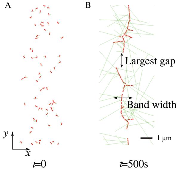
Snapshots of simulations showing the initial node distribution in (A) and nodes condensed into a ring structure in (B). The x-axis is parallel to the long axis of the cell; the y-axis is arc length along the cell circumference. Nodes are initially distributed according to a Gaussian distribution of standard deviation 0.9 μm along the x-axis and according to a uniform distribution along the y-axis [14]. Panel (B) shows largest gap and band width.
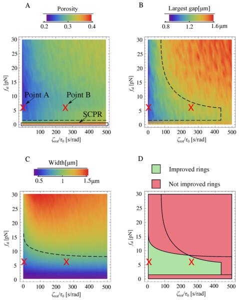
We examined the effect of local node alignment by measuring porosity, largest gap, and band width as a function of the two parameters introduced to the SCPR model: fal and ζrot/τ0. These two parameters measure the strength of the aligning force and torque, respectively: large fal values indicate a large aligning force while large ζrot/τ0 values indicate slow rotation of the polarization axis around the node center. All other parameters were kept fixed to the values of the SCPR model, as described in section 2. Figure 4 shows the results of simulations in which the aligning force and torque were varied. The values in the graphs are averages of 1000 simulations for each pair of parameter values. The values in figure 4 were calculated 500 s after the start of the simulations. This is how much time is required for the ring to assemble from a band of nodes [14].
Figure 4.
Results of Monte Carlo simulations of a model with local node alignment. (A)–(C) Average porosity, largest gap, and band width at 500 s, as a function of the parameter ζrot/τ0 (which measures the resistance to rotation of the polarization axis) and the aligning force fal. ζrot/τ0 was varied in steps of 10 s rad−1 and fal in steps of 2 pN. The results for each pair of parameter values are averages of 1000 simulations. The case fal = 0 pN reduces to the pure SCPR model (no local node alignment). Dashed lines indicate boundaries of regions of observable quantities consistent with the criteria for viable ring formation of the main text. (D) Plot showing the overlap of regions in parameter space with porosity, largest gap and band width that meet the criteria for viable ring formation of the main text.
The results of figure 4 show that the proposed aligning mechanism can generate rings that are improved compared to pure SCPR, depending on the parameter values. In the plots, the line fal = 0 pN corresponds to SCPR (since in this case there is no aligning, irrespective of the value of ζrot/τ0). We found that porosity (figure 4(A)) decreases with increasing aligning force fal. Forces of order a few piconewtons decrease the porosity by an amount that depends weakly on the value of the rotation time ζrot/τ0. This indicates that alignment promotes the formation of more complete rings. The largest gap in figure 4(B) also decreases with increasing aligning force, but only when the rotation time is sufficiently small (smaller than ~250 s rad−1). When nodes rotate very slowly, alignment occurs along the random directions in which the nodes happened to point initially, leading to few but large gaps. The effect of the aligning mechanism on band width is shown in figure 4(C). This figure shows that an increase in the aligning force beyond 10–15 pN generates wide rings. This effect is more pronounced at slow node rotation rates (large ζrot/τ0). The reason is that, similarly to panel B, very large aligning forces initiate ring segments that grow along incorrect directions determined by the random initial node orientation and spatial distribution.
In figure 4(D) we draw the region of parameter space in which the alignment generates viable rings (i.e. rings with properties consistent with experimental observations), using the following criteria: porosity < 0.33 (more than 2/3 of the circumference is populated by nodes), largest gap <1.4 μm (less than ≈10% of circumference length), and band width <0.9 μm (one half of initial width). The boundaries corresponding to these criteria are indicated by the dashed lines in figures 4(A)–(C). Parameters in the indicated range in figure 4(D) produce stable rings.
3.2. Specific examples
To further quantify and visualize ring morphologies in the region of parameter space corresponding to viable rings, we examined the two points marked A and B in figure 4. These two points have the same aligning force fal = 6 pN but different rotation rates to cover the two limits of high and low ζrot/τ0, respectively. This aligning force is nearly optimal: it is large enough to result in improved ring formation, small enough to be realistic, and larger values do not result in significant improvements.
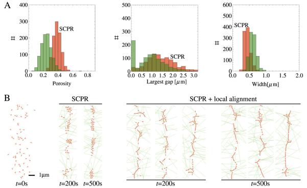
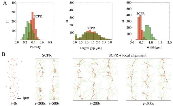
Figure 5 shows statistics of 1000 simulations and characteristic ring profiles for point A and for the pure SCPR model. The graphs in figure 5(A) show the improved porosity and largest gap distributions with respect to SCPR. The final-width distribution is not changed significantly with respect to SCPR. Note the high peak (≈23% of events) at zero largest gap: these are rings that completely span the cell circumference, see the snapshots in figure 5(B). Thus, for point A, the aligning mechanism helps in making cohesive rings and in distributing nodes evenly. In comparison with the snapshots obtained for SCPR, we see that the rings obtained with the local node alignment mechanism are more stable and have less clump formation.
Figure 5.
Statistics and snapshots of simulations using parameters corresponding to point A in figure 4 (fal = 6 pN, ζrot/τ0 = 1 s rad−1). (A) Distributions of porosity, largest gap and band width for point A (green) and SCPR (red) at 500 s (1000 simulations). The peak at largest gap = 0 μm corresponds to rings that fully span the cell circumference. (B) Snapshots of rings at 200 s and 500 s for pure SCPR and SCPR with local node alignment. In the latter case, rings with no vertical gaps form frequently.
Figure 6 shows the same statistics as figure 5 but for point B of figure 4. The overall behavior is similar, but the decrease in porosity and largest gap is less compared with point A. The width of the condensed band is larger. By being unable to rotate fast, nodes align along linear structures that extend in directions different from the ring axis. This results in larger gaps and widths.
Figure 6.
Same as figure 5 but for point B of figure 4 (fal = 6 pN, ζrot/τ0 = 250 s rad−1). Because of node resistance to rotation, side branches and gaps form during ring assembly.
An interesting feature of figures 5(B) and 6(B) is the appearance of linear node assemblies during the condensation process (see images of simulations at 200 s). These shapes are similar to the linear structures observed during the late stages of the condensation process in wild-type cells in figure 1(C).
3.3. Meshwork structures in simulations of cdc25-22 cells
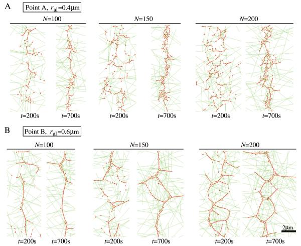
The simulations of section 3.2 illustrate the process of local alignment of nodes that come together over long distances through random search and capture. For wild-type cells, this aligning process aids in ring formation and generates transient linear structures. While linear parallel structures are less pronounced in wild-type cells, they are the typical case in cdc25-22 cells released from arrest (see figure 1(E)). We wanted to test whether our model can reproduce such structures when choosing parameter values that simulate the conditions of cdc25-22 cells. To compare with the results of section 2, we performed simulations using alignment parameters corresponding to those of points A and B in figure 4. We distributed the nodes in a band of standard deviation σ = 1.6 μm, as observed in those cells [14]. cdc25-22 cells have ≈100 cortical nodes [14]. In the simulations, we varied the number of nodes in the range 100–200, and we also varied the aligning distance ral in the range 0.4–0.6 μm, since for larger number of nodes and larger ral we could see structures very similar to the ones in figure 1(E). We left the number of filaments growing out of the nodes as two, even though in these cells the number of formin dimers per node can be larger than in WT cells (the results described below do not change much by increasing the number of filaments growing out of nodes).
In figure 7 we show examples of simulation snapshots for cdc25-22 cells at different times and for different parameter values (point A with ral = 0.4 μm and point B with ral = 0.6 μm). In both panels (A) and (B), bundled structures form during condensation, but the extent of large-scale meshwork formation varies. In panel (A), because of the wider initial band, the aligning process organizes the nodes into linear elements, before the nodes have enough time to come together into a narrow ring. This phenomenon is similar to the process of clump formation seen in simulations of very wide bands [26]. In panel (B), which is a simulation with a higher rotational friction coefficient and a larger aligning distance, the linear elements that form during condensation assemble into a large-scale meshwork structure. Interestingly, as we increase the number of nodes to approach 200, linear structures reminiscent of two parallel rings are noticeable. These structures have a similar morphology to the experimental images of cdc25-22 cells in figure 1(E). This indicates that, despite its simplicity, the model can capture the important features of ring assembly, namely the robust ring formation in wild-type cells and the development of meshwork structures in cdc25-22 cells.
Figure 7.
Snapshots of simulations for cdc25-22 cells showing the formation of meshwork structures. (A) Snapshots of rings at different times using the same aligning parameters as point A of figure 4 (fal = 6 pN, ζrot/τ0 = 1 s rad−1) with ral = 0.4 μm. Cases with different numbers of nodes are shown (N = 100, 150, 200). (B) Snapshots of rings at different times with the same aligning parameters as for point B of figure 4 (fal = 6 pN, ζrot/τ0 = 250 s rad−1) with ral = 0.6 μm.
3.4. Local alignment does not prevent clump instabilities
It was previously shown that the SCPR mechanism generates isolated clumps of nodes instead of rings when the parameter values are different from those observed experimentally [14]. Since the nodes pull one another, inhomogeneities in concentrations are amplified and the nodes tend to segregate into isolated clusters. When the time required for the band to condense to a ring is longer than the time required for clump formation within the interior of the band, condensation fails and isolated aggregates form [26]. The main criterion for successful ring formation is the relationship between the average length of actin filaments, λ = vpoltturn, and the initial band width, w: successful ring formation requires λ > Aw, where A is a number of order unity [26].
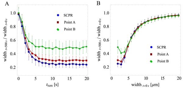
We have so far used parameter values corresponding to successful ring formation through pure SCPR (outside of the clump-formation region of parameter space). We wanted to test whether the aligning mechanism introduced in this paper prevents clump-formation instabilities in systems that would otherwise form clumps with pure SCPR. In figure 8 we varied λ and w by changing the parameters tturn and initial width, respectively. The aligning parameters were those of points A and B of figure 4. We found that the band fails to condense into rings for approximately the same λ and w values as for pure SCPR. Thus, local alignment did not assist ring assembly in systems that form clumps. This is expected: clumps form by connections and transport of nodes over long distances (of the order of the average filament length). Node alignment over small distances influences the structures of the clump aggregates, but its effect is short-ranged.
Figure 8.
Results of simulations showing the ratio of band width at 500 s over initial band width versus unconnected filament turnover time tturn and initial band width. Each point is an average of 100 simulations; error bars represent one standard deviation. (A) Ratio of band width versus tturn for parameter values corresponding to pure SCPR, and SCPR with the alignment mechanism. Two sets of alignment parameters are shown, corresponding to points A and B in figure 4. All other parameters were fixed to the values described in the main text. Changes in tturn influence the average filament length of unconnected filaments, tturnvpol, where vpol = 0.2 μm s−1. For small values of tturn, the band of nodes fails to condense and small aggregates form. The behavior is similar for all three cases. Note that the case of ‘point B’ leads to wider bands compared to the other two cases (see figure 6). (B) Ratio of band width versus initial width, as in panel (A). The number of nodes was changed in proportion to the initial width such that the average density of nodes remained unchanged. Very wide bands fail to condense to rings and the behavior is similar for all three cases.
We note that, depending on the node density, the number of nodes within a clump formed by SCPR could be large. By lining up, these nodes may be able to reach out to a neighboring clump structure. A meshwork with holes of size of order λ or larger may form in this manner. Here we do not consider the slow dynamics of such meshworks.
4. Discussion
In the model presented here, the components of the ring are pulled together over long distances by a search and capture mechanism. This is followed by stabilization of these components into linear structures by a local alignment mechanism. The model reproduces morphologies observed in wild-type and mutant cells. Our simple implementation of alignment motivates future experiments to resolve its precise molecular origin. Several molecules may contribute: myosin-II Myo2p, IQGAP Rng2p, Mid1p and actin cross-linkers fimbrin Fim1p and α-actinin Ain1p. These proteins play an important role in cytokinesis of fission yeast and other organisms but their precise mechanistic role remains to be resolved. The results of figures 4-8 describe our expectations of how cells with perturbed alignment properties may behave. For example, we expect the ring porosity to increase when the alignment strength (parameter fal) is reduced, see figure 4(A).
The alignment process proposed here could involve the recruitment of cytoplasmic proteins that stabilize the linear structures that form in a stochastic manner by search and capture. The cooperative nature of these interactions may be strong. We speculate that in systems with compromised nodes (such as deletions and mutations in the structural node component Mid1p [27, 40, 41]) this process may work in the reverse direction: bundling proteins may self-assemble into a linear structure first, recruiting missing node components in a second step. This could be the nature of the proposed ‘backup pathway’ for fission yeast ring assembly in Mid1p mutants [18, 42]. This would be consistent with the requirement of an active SIN pathway in these mutants [27, 40]: the SIN promotes ring maturation and constriction [43] so it could enhance the alignment mechanism.
The actin asters that are seen occasionally during fission yeast contractile ring assembly have provided evidence for the ‘leading cable’ model, an alternative to SCPR [19, 44-46]. In this model a Cdc12p spot at the center of the aster initiates the process of ring assembly. An interesting observation in figures 5-7 is that intersecting and star-shaped node structures spontaneously form in these simulations. We speculate that the asters are the result of such self-organization processes rather than the result of a single nucleating spot. In the simple model presented here, actin filaments polymerize along random directions and so we do not have a mechanism for actin aster formation. However, coupling between the direction of actin polymerization and local node alignment could generate star-shaped actin structures. This would be reminiscent of star formation in other systems of mixtures of motors and filaments [2, 3, 16, 47]. Future theoretical and experimental work looking into the precise kinetics of aster formation would help to answer this important question.
Here we described a process in fission yeast. We believe that the model may provide insights into the process of formation of actomyosin structures in other cell types and organisms, such as stress fibers and muscle fibers. There is evidence that these structures also assemble in a hierarchical manner [48].
Acknowledgments
This work was supported by NIH grants R21GM083928 to DV and R01GM086546 to J-QW.
References
- [1].Liverpool TB, Marchetti MC. Phys. Rev. Lett. 2003;90:138102. doi: 10.1103/PhysRevLett.90.138102. [DOI] [PubMed] [Google Scholar]
- [2].Cytrynbaum EN, Rodionov V, Mogilner A. J. Cell Sci. 2004;117:1381–97. doi: 10.1242/jcs.00919. [DOI] [PubMed] [Google Scholar]
- [3].Kruse K, Joanny JF, Julicher F, Prost J, Sekimoto K. Phys. Rev. Lett. 2004;92:078101. doi: 10.1103/PhysRevLett.92.078101. [DOI] [PubMed] [Google Scholar]
- [4].Kierfeld J, Khne T, Lipowsky R. Phys. Rev. Lett. 2005;95:038102. doi: 10.1103/PhysRevLett.95.038102. [DOI] [PubMed] [Google Scholar]
- [5].Backouche F, Haviv L, Groswasser D, Bernheim-Groswasser A. Phys. Biol. 2006;3:264–73. doi: 10.1088/1478-3975/3/4/004. [DOI] [PubMed] [Google Scholar]
- [6].Ziebert F, Aranson IS, Tsimring LS. New J. Phys. 2007;9:421. [Google Scholar]
- [7].Shlomovitz R, Gov NS. Phys. Rev. Lett. 2007;98:168103. doi: 10.1103/PhysRevLett.98.168103. [DOI] [PubMed] [Google Scholar]
- [8].Kraikivski P, Slepchenko BM, Novak IL. Phys. Rev. Lett. 2008;101:128102. doi: 10.1103/PhysRevLett.101.128102. [DOI] [PMC free article] [PubMed] [Google Scholar]
- [9].Chelakkot R, Lipowsky R, Gruhn T. Soft Matter. 2009;5:1504–13. [Google Scholar]
- [10].Brill-Karniely Y, Ideses Y, Bernheim-Groswasser A, Ben-Shaul A. ChemPhysChem. 2009;10:2818–27. doi: 10.1002/cphc.200900615. [DOI] [PubMed] [Google Scholar]
- [11].Stachowiak MR, O’Shaughnessy B. New J. Phys. 2008;10:025002. [Google Scholar]
- [12].Walcott S, Sun SX. Proc. Natl Acad. Sci. USA. 2010;107:7757–62. doi: 10.1073/pnas.0912739107. [DOI] [PMC free article] [PubMed] [Google Scholar]
- [13].Zumdieck A, Lagomarsino MC, Tanase C, Kruse K, Mulder B, Dogterom M, Jülicher F. Phys. Rev. Lett. 2005;95:258103. doi: 10.1103/PhysRevLett.95.258103. [DOI] [PubMed] [Google Scholar]
- [14].Vavylonis D, Wu JQ, Hao S, O’Shaughnessy B, Pollard TD. Science. 2008;319:97–100. doi: 10.1126/science.1151086. [DOI] [PubMed] [Google Scholar]
- [15].Shlomovitz R, Gov NS. Biophys. J. 2008;94:1155–68. doi: 10.1529/biophysj.107.111351. [DOI] [PMC free article] [PubMed] [Google Scholar]
- [16].Nédélec FJ, Surrey T, Maggs AC, Leibler S. Nature. 1997;389:305–8. doi: 10.1038/38532. [DOI] [PubMed] [Google Scholar]
- [17].Mogilner A, Wollman R, Civelekoglu-Scholey G, Scholey J. Trends Cell Biol. 2006;16:88–96. doi: 10.1016/j.tcb.2005.12.007. [DOI] [PubMed] [Google Scholar]
- [18].Pollard TD, Wu JQ. Nat. Rev. Mol. Cell Biol. 2010;11:149–55. doi: 10.1038/nrm2834. [DOI] [PMC free article] [PubMed] [Google Scholar]
- [19].Bathe M, Chang F. Trends Microbiol. 2010;18:38–45. doi: 10.1016/j.tim.2009.10.002. [DOI] [PMC free article] [PubMed] [Google Scholar]
- [20].Goyal A, Takaine M, Simanis V, Nakano K. Cytoskeleton. 2011;68:69–88. doi: 10.1002/cm.20500. [DOI] [PMC free article] [PubMed] [Google Scholar]
- [21].Drake T, Vavylonis D. HFSP J. 2010;4:122–30. doi: 10.2976/1.3385659. [DOI] [PMC free article] [PubMed] [Google Scholar]
- [22].Motegi F, Nakano K, Mabuchi I. J. Cell Sci. 2000;113:1813–25. doi: 10.1242/jcs.113.10.1813. [DOI] [PubMed] [Google Scholar]
- [23].Wu JQ, Siirotkin V, Kovar DR, Lord M, Beltzner CC, Kuhn JR, Pollard TD. J. Cell Biol. 2006;174:391–402. doi: 10.1083/jcb.200602032. [DOI] [PMC free article] [PubMed] [Google Scholar]
- [24].Coffman VC, Nile AH, Lee IJ, Liu H, Wu JQ. Mol. Biol. Cell. 2009;20:5195–210. doi: 10.1091/mbc.E09-05-0428. [DOI] [PMC free article] [PubMed] [Google Scholar]
- [25].Laporte D, Coffman VC, Lee IJ, Wu JQ. J. Cell Biol. 2011;192:1005–21. doi: 10.1083/jcb.201008171. [DOI] [PMC free article] [PubMed] [Google Scholar]
- [26].Ojkic N, Vavylonis D. Phys. Rev. Lett. 2010;105:048102. doi: 10.1103/PhysRevLett.105.048102. [DOI] [PMC free article] [PubMed] [Google Scholar]
- [27].Hachet O, Simanis V. Genes Dev. 2008;22:3205–16. doi: 10.1101/gad.1697208. [DOI] [PMC free article] [PubMed] [Google Scholar]
- [28].Wu JQ, Pollard TD. Science. 2005;310:310–4. doi: 10.1126/science.1113230. [DOI] [PubMed] [Google Scholar]
- [29].Wu JQ, Bähler J, Pringle JR. Mol. Biol. Cell. 2001;12:1061–77. doi: 10.1091/mbc.12.4.1061. [DOI] [PMC free article] [PubMed] [Google Scholar]
- [30].Nakano K, Satoh K, Morimatsu A, Ohnuma M, Mabuchi I. Mol. Biol. Cell. 2001;12:3515–26. doi: 10.1091/mbc.12.11.3515. [DOI] [PMC free article] [PubMed] [Google Scholar]
- [31].Skau CT, Kovar DR. Curr. Biol. 2010;20:1415–22. doi: 10.1016/j.cub.2010.06.020. [DOI] [PMC free article] [PubMed] [Google Scholar]
- [32].Takaine M, Numata O, Nakano K. EMBO J. 2009;28:3117–31. doi: 10.1038/emboj.2009.252. [DOI] [PMC free article] [PubMed] [Google Scholar]
- [33].Celton-Morizur S, Bordes N, Fraisier V, Tran PT, Paoletti A. Mol. Cell Biol. 2004;24:10621–35. doi: 10.1128/MCB.24.24.10621-10635.2004. [DOI] [PMC free article] [PubMed] [Google Scholar]
- [34].Vavylonis D, Kovar DR, O’Shaughnessy B, Pollard TD. Mol. Cell. 2006;21:455–66. doi: 10.1016/j.molcel.2006.01.016. [DOI] [PMC free article] [PubMed] [Google Scholar]
- [35].Kovar DR, Pollard TD. Proc. Natl Acad. Sci. USA. 2004;101:14725–30. doi: 10.1073/pnas.0405902101. [DOI] [PMC free article] [PubMed] [Google Scholar]
- [36].Isambert H, Venier P, Maggs AC, Fattoum A, Kassab R, Pantaloni D, Carlier MF. J. Biol. Chem. 1995;270:11437–44. doi: 10.1074/jbc.270.19.11437. [DOI] [PubMed] [Google Scholar]
- [37].McCullough BR, Blanchoin L, Martiel JL, De la Cruz EM. J. Mol. Biol. 2008;381:550–8. doi: 10.1016/j.jmb.2008.05.055. [DOI] [PMC free article] [PubMed] [Google Scholar]
- [38].Smith MB, Li H, Shen T, Huang X, Yusuf E, Vavylonis D. Cytoskeleton. 2010;67:693–705. doi: 10.1002/cm.20481. [DOI] [PMC free article] [PubMed] [Google Scholar]
- [39].Yang Y, Meyer RB, Hagan MF. Phys. Rev. Lett. 2010;104:258102. doi: 10.1103/PhysRevLett.104.258102. [DOI] [PubMed] [Google Scholar]
- [40].Huang Y, Yan H, Balasubramanian MK. J. Cell Biol. 2008;183:979–88. doi: 10.1083/jcb.200806151. [DOI] [PMC free article] [PubMed] [Google Scholar]
- [41].Wachtler V, Huang Y, Karagiannis J, Balasubramanian MK. Mol. Biol. Cell. 2006;17:3254–66. doi: 10.1091/mbc.E05-11-1086. [DOI] [PMC free article] [PubMed] [Google Scholar]
- [42].Roberts-Galbraith RH, Gould KL. Genes Dev. 2008;22:3082–8. doi: 10.1101/gad.1748908. [DOI] [PubMed] [Google Scholar]
- [43].McCollum D, Gould KL. Trends Cell Biol. 2001;11:89–95. doi: 10.1016/s0962-8924(00)01901-2. [DOI] [PubMed] [Google Scholar]
- [44].Arai R, Mabuchi I. J. Cell Sci. 2002;115:887–98. doi: 10.1242/jcs.115.5.887. [DOI] [PubMed] [Google Scholar]
- [45].Yonetani A, Lustig RJ, Moseley JB, Takeda T, Goode BL, Chang F. Mol. Biol. Cell. 2008;12:2208–19. doi: 10.1091/mbc.E07-07-0731. [DOI] [PMC free article] [PubMed] [Google Scholar]
- [46].Mishra M, Oliferenko S. Curr. Biol. 2008;18:R247–50. doi: 10.1016/j.cub.2008.01.029. [DOI] [PubMed] [Google Scholar]
- [47].Haviv L, Brill-Karniely Y, Mahaffy R, Backouche F, Ben-Shaul A, Pollard TD, Bernheim-Groswasser A. Proc. Natl Acad. Sci. USA. 2006;103:4906–11. doi: 10.1073/pnas.0508269103. [DOI] [PMC free article] [PubMed] [Google Scholar]
- [48].Sanger JW, Kang S, Siebrands CC, Freeman N, Du A, Wang J, Stout AL, Sanger JM. J. Muscle Res. Cell Motil. 2005;26:343–54. doi: 10.1007/s10974-005-9016-7. [DOI] [PubMed] [Google Scholar]


