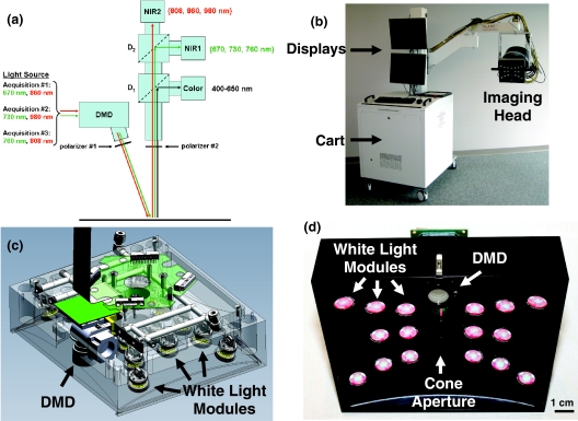
Figure 1.
Clinical imaging system working in the spatial frequency domain: (a) Schematics of the system showing the light paths for all wavelengths into the system imaging head. The light from the NIR light source is propagated to the DMD and projected onto the field through polarizer #1. Light is then collected though polarizer #2 and split onto the three cameras using dichroic mirrors. Wavelengths shown in green and red are collected by NIR cameras 1 and 2, respectively. (b) Picture of the clinical imaging system composed of a cart containing the NIR light source, control electronics, computer, mast, and arm holding the adjustable imaging head. (c) Computer-aided design semi-transparent drawing of the illumination section of the imaging head. Note white light LED modules and the DMD projection module. (d) Bottom view of the actual illumination section of the imaging head. Note the white light LED modules, the DMD projection optics, and the cone aperture.

