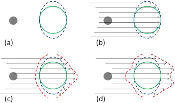
Fig. 2.

An illustration of the four essential steps in creating the bsPTV (red contour) from a CTV (green contour) with a dense object (grey sphere) along the beam path. (a) The CTV is expanded laterally away from the beam axis using the expected motion margin (IM) and setup margin (SM). (b) From a given beam angle, ray tracing is performed to calculate the radiological path length of each ray from the source to the both distal and proximal surface of the laterally expanded CTV (blue contour). (c) The fraction of the total radiological range calculated in previous step is used to the distal margins per ray. (d) Correction for interplay effect of setup and range error is accounted by applying the correction kernel and the radiological path length margins are converted to physical depth margins.
