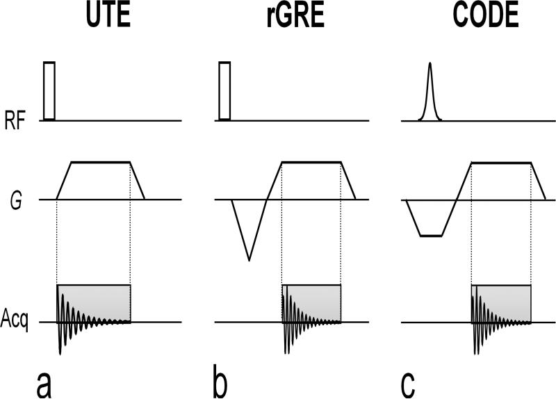
FIG. 1.
Pulse sequence diagrams of 3D UTE, 3D radial GRE (rGRE), and CODE. (a) In the 3D UTE, a square pulse is used for spin excitation and data acquisition starts during the readout gradient ramp to achieve the shortest acquisition delay possible. Since no dephasing gradient is applied for readout, a FID is acquired during acquisition. (b) In rGRE, a square pulse is also used for excitation. Data is acquired during the readout gradient following an initial dephasing (or pre-dephasing) gradient, and thus, a gradient echo is acquired instead of the FID. A partial gradient-echo acquisition scheme is employed to minimize TE. (c) In CODE, slab selection and pre-dephasing are performed with the same gradient. In other words, a pre-dephasing gradient is applied during, not after, spin excitation. Hence, a gradient echo is acquired as in rGRE. A slab-selective pulse such as a sinc or a hyperbolic secant pulse can be used for spin excitation. Because the acquisition time will usually be much longer than the pulse duration (i.e. Tacq is on the order of a few milliseconds or less, whereas Tp is usually ~100 – 300 microseconds), the peak of the gradient echo forms soon after the start of the acquisition period and, thus, the gradient echoes used to fill k-space in each radial direction are asymmetric about the origin of k-space.

