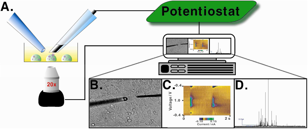
Figure 2.
Instrumental setup for a CFM electrochemistry experiment. (A) CFM (right) is placed on a single cell with the stimulating pipette (left) near the cell. (B) Bright field image of the experimental setup showing the CFM and stimulating pipette positioned on a single mast cell. (C) Representative color plot obtained by FSCV. (D) Representative amperometric trace obtained using CFMA on a mast cell. Figure (C) modified with permission from American Chemical Society from Reference 25.

