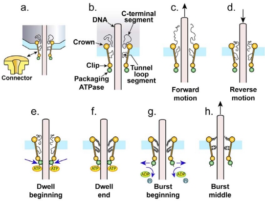
Figure 2.
The components of the proposed type 1 cycle, side view. To simplify the drawing, the correct symmetry of the ATPase multimer, assuming it to be five-fold, is not represented. (a) The connector (yellow) is shown as represented in Figure 1 (lower left, in isolation) and also at higher resolution while embedded in the shell (light blue) with terminase (green) attached to it. (b) The components of the signaling center of the motor are shown at higher magnification with the labeling used in the text. (c) The motor is shown at the beginning of a cycle with DNA molecule undergoing forward thermal motion, i.e., thermal motion into the cavity of the shell. (d) The motor is shown with DNA molecule undergoing reverse thermal motion. (e) The motor is shown at the beginning of a dwell, with ATP (yellow oval with orange border) bound to terminase and terminase bound to DNA molecule. (f) The motor is shown at the end of a dwell with mobile peptide segments activated; coiling illustrates activation, but the true activated conformation is not known. (g) The motor is shown at the beginning of a burst, with terminase no longer binding the DNA molecule, ATP cleaved and mobile peptide segments pushing on the DNA molecule as they begin to deactivate. (h) The motor is shown in the middle of a burst. As the burst proceeds, the motor returns to its state in (c, d).

