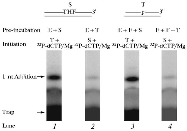
Fig. 12.

DNA synthesis step in LP BER. Schematic representations of APE1-treated THF-DNA substrate (S), a LP BER intermediate, and the DNA trap (T) are illustrated above the phosphorimage of the gels. E and F denote polymerase β and FEN1, respectively. The DNA synthesis reaction was performed by polymerase β alone or polymerase β and FEN1 in the presence of excess DNA trap. The repair reaction mixture was assembled on ice, either with polymerase β alone (lane 1) and substrate DNA or with polymerase β and FEN1 (lane 3) and substrate DNA, respectively. The reactions were initiated by temperature jump and the addition of a mixture of [α-32P]dCTP, dATP, dGTP, TTP, DNA trap, and MgCl2 (lanes 1 and 3). In another set of reaction mixtures, polymerase β or polymerase β and FEN1 were mixed with the DNA trap first, and the reactions were initiated by temperature jump and adding a mixture of [α-32P]dCTP, dATP, dGTP, TTP, substrate DNA, and MgCl2 (lanes 2 and 4), respectively. Reaction mixtures were incubated for 10 s and analyzed. The positions of the 1-nt addition product and free-labeled trap are indicated.
