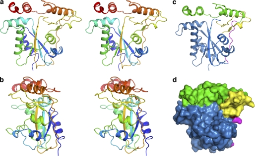
FIGURE 2.
Structure of apo-CblC. a and b, stereoview of apo-t-CblC in two orientations, related by a 90° rotation. Ribbon (c) and space-filling (d) representations of the arrangement of the apo-t-CblC modules. The core module is shown in blue, the cap is displayed in green, the linker is in pink, and the two β-sheet antiparallel insertion of the core domain is shown in yellow.

