Fig. 6.
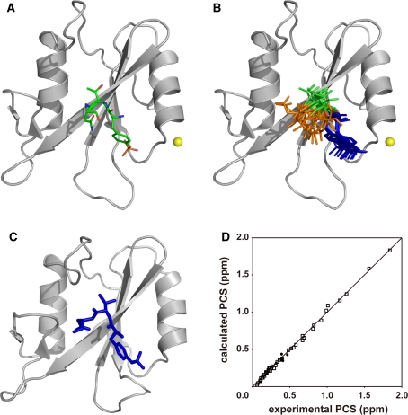
The docking structure of Grb2 SH2 and the pYTN tripeptide. a The lowest energy structure. Grb2 SH2 and the tripeptide are represented as ribbon and stick models, respectively. The position of the lanthanide ion is represented as a yellow sphere. b Ensemble of the 10 lowest energy structures. Grb2 SH2 moieties are superimposed. pTyr, Thr, and Asn are colored blue, green, and orange, respectively. c X-ray crystal structure of Grb2 SH2 complexed with a phosphorylated peptide (PSpYVNVQN) (Nioche et al. 2002, 1jyr.pdb). The corresponding residues of the peptide are displayed as a stick model. The structures were drawn using the program PyMOL (DeLano 2002). d Comparison of experimental and back-calculated PCSs of proton signals of the low-affinity peptide (filled circles) and backbone amide proton signals of Grb2 SH2 (open squares) in complex with Tm3+. The PCS calculation was carried out for the lowest energy structure of the complex

