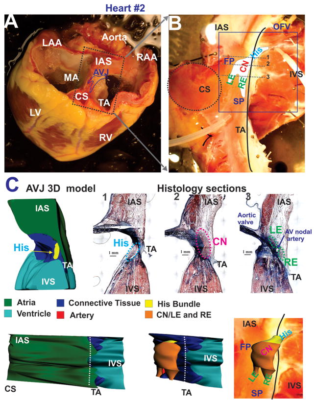
Figure 1.
Explanted heart #2 and anatomy of the experimental preparation. Panel A: A photograph of explanted failing human heart #2 before dissection. The approximate borders of the AV junction (AVJ) are shown by the dark blue line. Abbreviations: RV and LV: right and left ventricles; MA and TA: mitral and tricuspid valve annulus; RAA and LAA: right and left atrial appendages; IAS: interatrial septa, CS: coronary sinus. Panel B: A photograph of the coronary-perfused human AVJ preparation with an optical field of view (OFV) which included: compact node (CN), leftward (LE) and rightward extensions (RE), and the bundle of His (His). Gray dotted lines show the location of histological sections illustrated in panel C. Abbreviations: SP and FP: slow and fast pathways; IVS: intraventricular septa. Panel C: Histology sections through the NH region (His), compact AV node (CN), and extensions (RE and LE) from sites 1–3 in panel B. Panel D: 3D anatomical reconstruction of AVJ #2 from histological sections. Top - Cross-section in projection zx, which corresponds to histology slide 1 in panel C. Middle and Bottom –endocardial projection (xy) of the AVJ with and without the atrial myocardial layer displayed.

