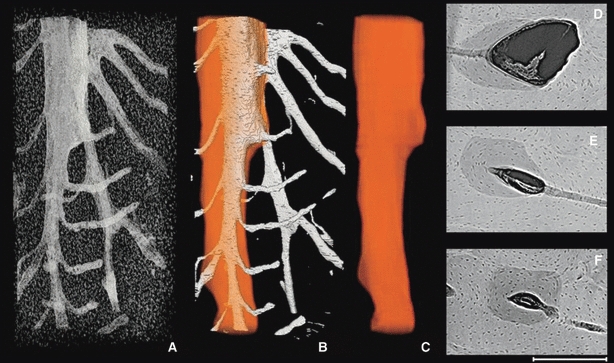
Fig. 5.

Representative 3D (A–C) and 2D (D–F) images of a drifting osteon from posterior periosteal surface (Fig. 1). The porous structures alone (A), vascular porosity with the superimposed osteon outline (B) and finally the osteon outline alone (C) are portrayed in 3D. The 2D images (D–F) are 100 μm average projections roughly corresponding to the adjacent position in the 3D render. The sequence clearly shows that the osteon began (F) as roughly cylindrical and then subsequently began to drift (D,E). The cutting cone of the drifting osteon extends beyond the superior aspect of the scan, although a portion of it is evident within (D). The total length of the 3D render is 1.7 mm. Scale bar at bottom right is 250 μm long.
