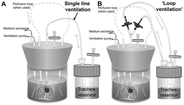
Figure 1.
Bioreactor schematic diagrams. Lung is contained within main bioreactor, with cannulae in the trachea and pulmonary artery. Pulmonary arterial cannula is connected to a perfusion loop to enable vascular perfusion. Tracheal cannula connects to a separate tracheal reservoir, which can be filled with culture medium to allow ventilation with medium, or can be empty to enable ventilation with air. A: Schematic showing single-line ventilation, wherein medium follows the same path into and out of the lung during ventilation; B: Schematic demonstrating ‘loop’ ventilation, wherein medium follows a different path during inhalation and exhalation, thereby delivering fresh medium to the lung with each breath. One-way valves are indicated in blue, while grey discs indicate air filters.

