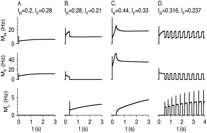
Figure 11. Response of the RS-LTS-FS network to step inputs I RΘ(t) and I FΘ(t) to the RS and FS neurons.
Parameters are listed in Table 2. Time courses of M R (top panels), M F (middle panels) and M L (middle panels) are plotted. (A) I R = 0.2, I F = 0.28. M L = 0 for all times. (B) I R = 0.28, I F = 0.21. M F = 0 for large t. (C) I R = 0.44, I F = 0.33. M F and M L are non-zero for large t. (D) I R = 0.316, I F = 0.237. The network oscillates at large t. RS neuron oscillate between a more active state and a less active state. FS neurons fire during the more active state of RS neurons, and LTS neurons fire during the less active state of RS neurons.

