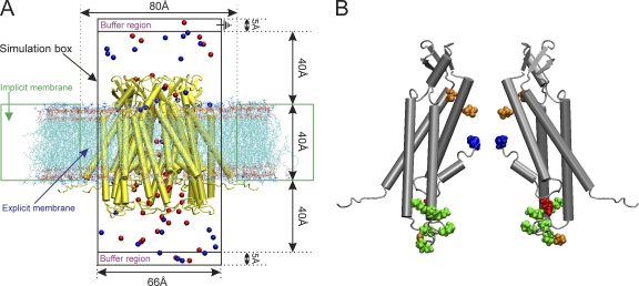
Figure 4.
(A) Schematic representation of the GCMC/BD system for Cx26 hemichannels. A Cx26 hemichannel (yellow) inserted into the explicit POPC membrane system was integrated into the implicit membrane system of the GCMC/BD program to ensure a tight seal between the irregular conical surface of the Cx26 channel and the implicit membrane. The boundaries of the implicit and explicit membranes are indicated by the dotted green lines. The simulation box (66 × 66 × 120 Å) was separated by the channel/membrane into two compartments, each containing 100 mM KCl. The buffer region maintains the chemical potential in the two compartments by creating and destroying ions with a GCMC algorithm. The upper compartment (extracellular part of the channel) was defined as the ground in voltage applications. 20 replicate 450-ns simulations were performed at each of seven voltages, ±150, ±100, ±50, and 0 mV, to plot the I-V relations. Blue circles, K+; red circles, Cl−. (B) Positions of modified residues identified by Locke et al. (2009) that would alter the distribution of charge in the Cx26 channel pore, shown in a side view of two opposite subunits of the completed crystal structure. The positions of acetylated residues are colored as follows: blue, Met1; red, K15; green, K102, K103, K105, K108, K112, and K116 in CL/TM2; orange, γ-carboxyglutamated residues E42, E47, and E114.

