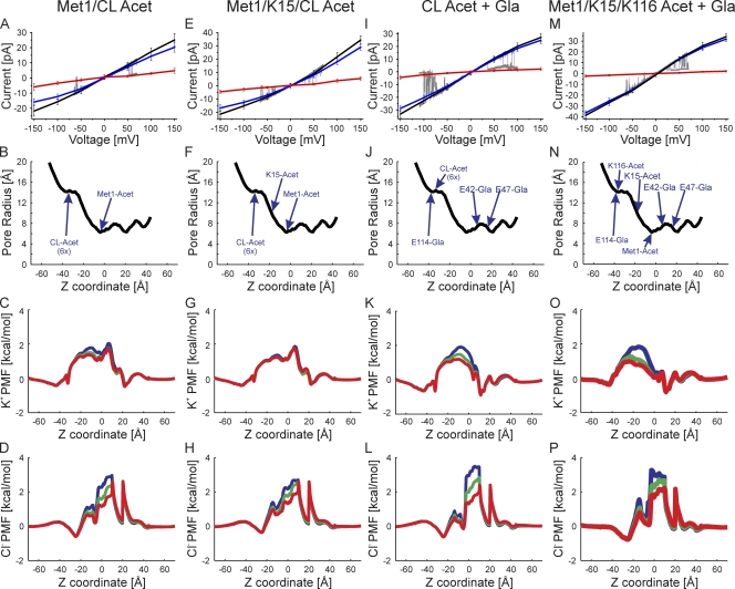
Figure 6.
Superimposition of experimental I-V relations (gray traces) and those computed by GCMC/BD simulations with the charge effects of the indicated protein modifications. (A) The correspondence between slight outward rectification (Fig. 3 E) and simulated channel with neutralization of Met1 and six internal lysine residues in TM2/CL. The charge neutralizations mimic acetylation. The black line is the total current, the blue line is the K+ current, the red line is the Cl− current, and the gray line is the single-channel current trace. (B) The pore radius of the simulated channel structure plotted against the z coordinate. The positions of the modified atoms are shown. The six acetylated lysine residues at the tip of TM2/CL are grouped into one position and labeled “CL-Acet 6x.” (C) The PMF of K+ at three voltages, 150 mV (blue), 0 mV (green), and −150 mV (red), plotted against the z coordinate. (D) The PMF of Cl− determined at the same three voltages. (E–H) Outwardly rectifying experimental I-V relation corresponds to simulated I-V relations in which Met1, K15, and six lysine residues in TM2/CL are neutral-mimicking acetylation. (I–L) Inward sigmoidal experimental I-V relation corresponds to simulated I-V relations in which the six lysine residues in TM2/CL are neutralized (acetylated) and the three glutamate residues are modified by γ-carboxyglutamation (Gla). (M–P) Slightly inward rectifying experimental I-V relations correspond to simulated I-V relations in which Met1, K15, and K116 are neutralized (acetylated) and the three glutamate residues are modified by γ-carboxyglutamation (Gla).

