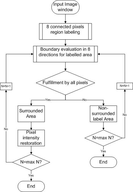
Figure 3.

Flow chart for the bounded area evaluation (BAE) algorithms. In this figure, the main structure of BAE algorithms is illustrated. The input image will undergo a region labeling process of eight connected pixels. After that an evaluation of boundary of each label cluster is performed. Two errors are expected to be found: the surrounded area represents the lost detail; the non-surrounded label represents noises and redundant information. The undesired noise will be eliminated while the lost detail will be recovered.
