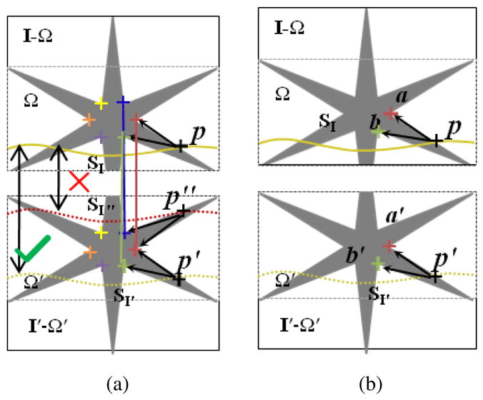
Figure 3.

Feature-guided seam matching in the moving image. The correspondences in I and I′ are shown with the colored crosses. From (a) we can see the seams SI″ and SI′ may have same cost values due to the similar structure they passed. Obviously, SI″ is not correct. We can use the matched features to guide the seam matching. For the point p ∈SI, the features in a local region form a structure topology of p that help to reject incorrect matching. An example matched seam in the moving image is showed in (b). where
 denotes the neighboring system and β is the parameter to balance the two terms. Suppose label lp is defined by the displacement dp. let ΔII′ be (I(p − I′(p + dp))2. The data term for each node on the interface seam S is defined, as follows.
