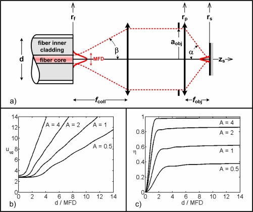
Fig. 1.
Confocal imaging with a DCF. (a) Light propagation schematic. Illumination light originates from the core of the DCF defined by its MFD (taken at the 1/e2 intensity point) and numerical aperture (illumination half-angle β). It is collimated with a lens of focal length fcoll and fills an objective lens (of focal length fobj, aperture 2aobj, illumination cone half-angle α). Light collection is performed through the inner cladding of the DCF (of diameter d). Light propagates along the z-axis and rf, rp and rs define the radial coordinates at the fiber, objective lens pupil and sample planes, respectively. (b) Optical sectioning (u1/2) for a perfect plane reflector as a function of the ratio d/MFD for different values of the pupil filling factor A. c) Excitation efficiency (η) for a perfect plane reflector at focus (u = 0) as a function of the ratio d/MFD for different values of A.

