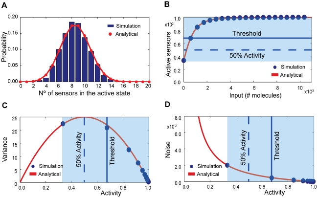
Figure 3. The intrinsic fluctuations follow a binomial distribution and can maximize their variance away from the threshold of the response curve.
(A) Comparison between Eq. (5) (in dark blue) and numerical simulation (red line). Total number of sensors is 20; the initial number of input molecules is 224; K = 100; c = 0.01; n = 4; fR = 0.01 s−1; fT = 0.01 s−1; bR = 1 s−1; and bT = 100 s−1. (B) The threshold of the response (the midpoint between the basal and saturation levels) need not coincide with the level of input at which 50% of the sensors are active. (C) The maximum of the variance in the system, which is always located at the 50% of activity level, need not coincide with the threshold value of the input signal. (D) The intrinsic noise decreases with increasing input because more sensors become activated. In (B, C, D), the dark blue dots represent numerical simulation, the red curve the analytical solutions from Eqs. (1) and (10), and the light blue box shows the dynamic range of activity. The total number of sensors in the system is 100; K = 2; c = 0.1; fR = 0.01 s−1; fT = 0.01 s−1; bR = 10 s−1; and bT = 100 s−1.

