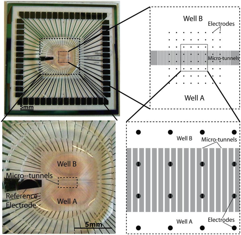
Figure 1.
The left top panel shows a microtunnel PDMS device integrated with an MEA. The device is aligned to and seated on the MEA. The left bottom panel shows the enlarged view of the device. The right top and right bottom schematics show the internal configuration of the integration of a device and an MEA. After alignment, all the electrodes are divided into three groups, by location: Well A, microtunnel region and Well B.

