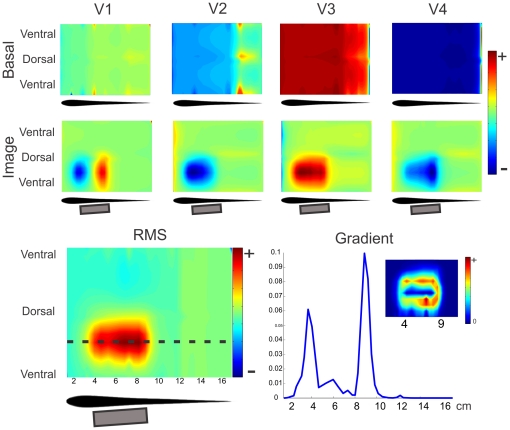
Figure 8. Image of a large metal object.
Two dimensional plots correspond to the images on the skin, where it was cut through the ventral intersection with the saggital plane, stretched perpendicularly to the longitudinal axis, to cover a rectangle. The horizontal scale corresponds to the distance in cm from the frontal tip along the skin through the horizontal plane. Top: Images generated on the skin of MoGO by a 2 by 5 cm cylinder placed almost parallel to the lateral skin at different instances of the EOD corresponding to the peaks of the four main components. Top Row: images, at the head and trunk regions, of the basal currents for each wave. Bottom Row: the electric image (at the same region) as the difference between currents with and without the cylinder. Bottom Left: RMS image of MoGO's body. Bottom Right: Longitudinal profile of the gradient of the RMS electric image showing two peaks signaling the position of the edges of the object. Inset: 2D mapping of the gradient of the RMS image shows the correlation between high gradient and the edges of the object.

