Fig. 1.
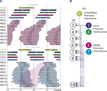
Bilateral phase diagram of the timing pattern (A) and hemilateral circuit diagram of the premotor heart (HN) interneurons of the leech heartbeat central pattern generator (CPG) and the postsynaptic heart (HE) motor neurons (B). HE motor neurons and HN interneurons are indexed by the body side and the midbody ganglion number they reside in (see also methods). Standard colors are used for the HN interneurons (see Terminology and color code in methods). A: bilateral phase diagram of the premotor HN interneurons and the entire HE motor neuron ensemble for the peristaltic (top) and synchronous (bottom) coordination mode. Each box represents the average duty cycle of a neuron's activity with the vertical line in the center representing the middle spike (±SD), the left edge the first spike, and the right edge the last spike, respectively (error bars omitted for clarity). Phase reference is the middle spike of the peristaltic HN(4) interneuron and is assigned 0 phase. To illustrate the side-to-side phase relations of the HE motor neurons, the diagram of the peristaltic mode was copied into the diagram of the synchronous mode (translucent pink boxes, no error bars). Note that HE motor neurons come together in phase in both the front and rear segments. B: HE motor neurons of segments 3 to 18 receive staggered input from ipsilateral premotor HN interneurons: from the HN(3) and HN(4) (front premotor HN interneurons), from the HN(6) and HN(7) (middle premotor HN interneurons), and from the unidentified HN(X) interneuron. Large colored circles are cell bodies (indexed by midbody segment number), lines indicate cell processes, and small circles indicate inhibitory chemical synapses. [Adapted from Norris et al. 2007b.]

