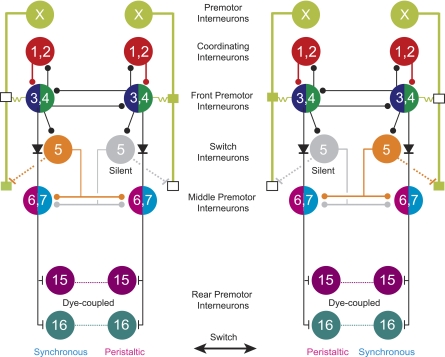
Fig. 12.
Circuit diagrams show the synaptic connections among all known interneurons of the heartbeat CPG in its 2 coordination modes: left synchronous/right peristaltic and left peristaltic/right synchronous. Standard colors are used for the HN interneurons (see methods). Small vertical lines indicate excitatory synapses, small boxes along the HN(X) interneurons' axons in segments 3 to 6 are spike initiation sites, diodes indicate rectifying electrical synapses, and resistors indicate the electrical connection between the HN(3) and HN(4) interneurons and the anterior spike initiation site of the HN(X) interneuron. For simplicity, cells with similar input and output connections and function are combined. HN(1) and HN(2) interneurons (red circles) coordinate the activity of the HN(3) and (4) interneurons, and together these 4 pairs of interneurons form the beat-timing network. Switches in coordination mode of the CPG are associated with switches in which one HN (5) interneuron (the switch interneuron) is active (orange, synchronous side) and which one is silent (gray, peristaltic side). Dashed processes from the HN(5) interneuron to the posterior initiation site in segment 6 of the HN(X) interneuron indicate an indirect excitatory pathway. The newly identified rear premotor HN(15) and HN(16) interneurons receive excitatory input from both middle premotor interneurons. Diagrams are based on data from Calabrese (1977) and Norris et al. (2007a, 2007b).

