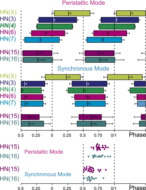
Fig. 8.
Bilateral phase diagram of all premotor HN interneurons is shown for the peristaltic (top) and synchronous (bottom) coordination mode. Each box represents the average duty cycle of a neuron's activity with the vertical line indicating the middle spike (see Fig. 1 for details). Absolute phase reference (phase 0) is the HN(4) interneuron on the peristaltic side. The HN(15) and HN(16) interneurons fire in phase in both coordination modes. They contribute to the rear-to-front progression in the peristaltic mode and to the front-to-rear progression in the synchronous mode. Standard colors are used for the HN interneurons (see methods). Data for the front and middle heart premotor interneurons and for the HN(X) interneuron are from Norris et al. (2007b). To illustrate the variability in phasing, the middle spike phases of individual rear premotor HN interneurons are shown at bottom. Middle spike phases were determined in both coordination modes for each rear HN interneuron.

