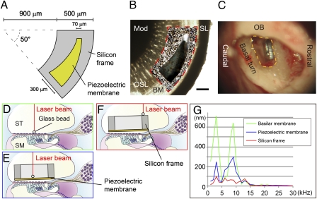
Fig. 3.
Sound transmission from the external auditory canal to a piezoelectric device implanted in the cochlea. (A) Design of an implantable piezoelectric device. (B) A merged image of an implantable piezoelectric device and the basal turn of the guinea pig cochlea. To determine the radius of curvature of the outer border and the inner border of the fan-shaped silicon frame and location of the slit in the silicon frame, we measured radius of curvature of the cochlear basal turn, length between an inner edge of the spiral ligament (SL) and a medial end of the osseous lamina (OSL) where the device will be implanted, and length of the basilar membrane (BM; length between inner edge of spiral ligament and lateral end of osseous lamina). An outline of the silicon frame is shown by a red dotted line. The silicon frame is positioned on the osseous spiral lamina, and the slit of the device is located adjacent to the BM. Mod, cochlear modiolus. (Scale bar: 200 μm.) (C) A microscopic view of an implanted device in the basal turn of the guinea pig cochlea. The yellow dotted line indicates an opening in the basal turn of the cochlea. OB, otic bulla. (D–F) Schematic drawings of measuring vibration amplitudes using a laser Doppler vibrometer. A glass bead is placed on the BM (D), piezoelectric membrane (E), or silicon frame (F). Red lines indicate a laser beam from a laser Doppler vibrometer. SM, scala media; ST, scala tympani. (G) Vibration amplitudes of a BM (green), piezoelectric membrane (blue), and silicon frame (red) corresponding to frequencies of applied sounds.

