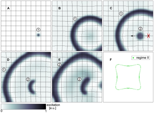
Figure 5. Spiral wave formation following a point stimulus.
(A) A wave (1) forms as response to a point stimulus ( ). (B) Wave (1) propagates radially and causes stretch and initiation of a wave (2) due to depolarizing stretch activated current
  (
( ). (C) The wave (2) is unidirectionally blocked (indicated by arrows) in the mechanically induced vulnerable zone (
 ). (D) Wave (2) forms a pair of counter rotating spiral waves (
 ). (E) Spiral wave pair (2) after one rotation (
 ). (F) Enclosed by green region: pacemaking regime, excluded by green region: quiescence regime, green region: critical region where a point stimulus initiates spiral wave dynamics. System size as in Figure 2 and
  .
.

