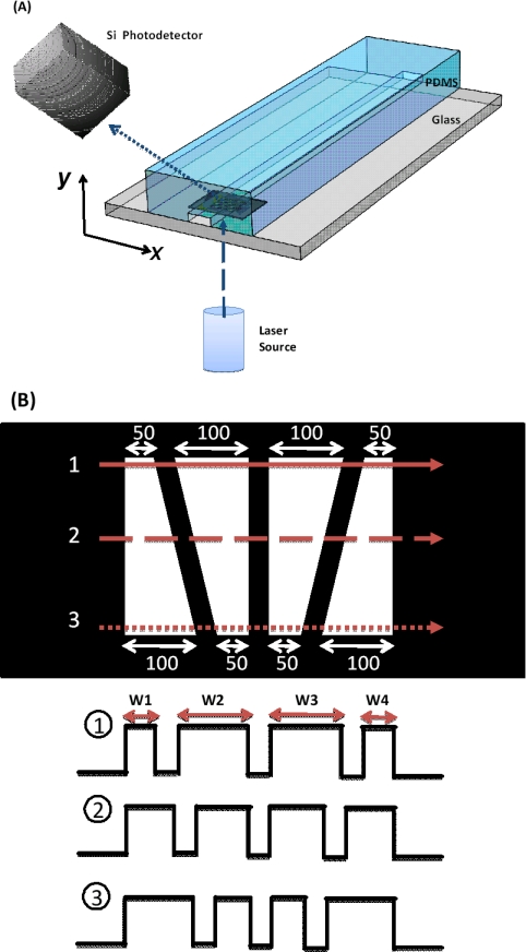
Figure 1.
(a) Schematic of our optical-coding microfluidic device setup. (b) An illustration of spatial pattern for optical coding. Three representative forward-scattering signals are shown for particles travelling through different positions of the microfluidic channel. Each trapezoidal slit has its base lengths of 100 μm and 50 μm. The width of each peak, W1 through W4, in the signal is used to acquire the position of particles along the x-direction. The method to find the position along the y-direction will be discussed later.

