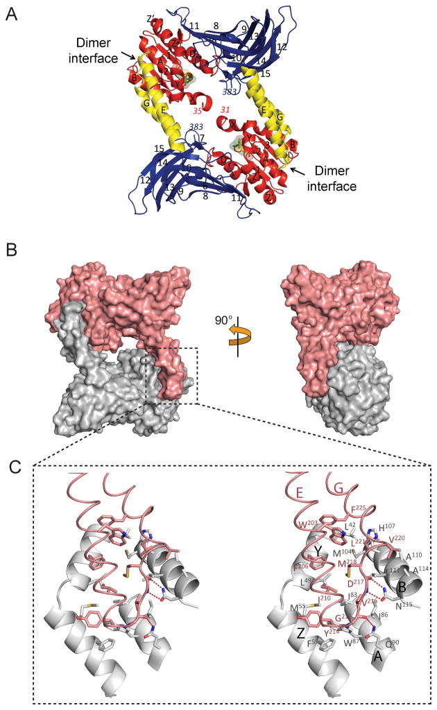
Figure 3. Dimer formation of AtPRMT10.
(A) The crystal structure of an AtPRMT10 dimer. The structure is colored and labeled as in Figures 1A–B. The location of each dimer interface is highlighted by an arrow. The dimer is formed by the interaction between the dimerization arm of one monomer and the outer surface of the SAM binding domain of the other monomer. (B) A surface representation of two views of an AtPRMT10 dimer, with two monomers are colored in gray and pink, respectively. (C) An expanded stereo-view of the dimer interface. Two monomers are colored as in Figure 2B. Residues involved in dimer formation are shown as sticks and labeled. Hydrogen bonds are indicated by red dashed lines.

