
Figure 4.
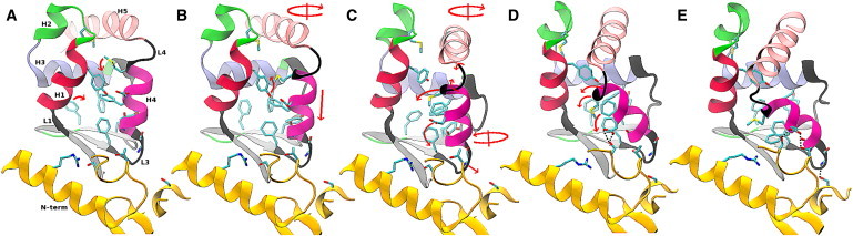
Snapshots from simulation 2 (see text) that illustrate the transition mechanism. Arrows indicate the conformational change associated with the snapshot that leads to the structure in the next snapshot. Circular arrows indicate a rigid rotation around the axis drawn through the arrow. The free energy corresponding to each snapshot is indicated in Fig. 3. Panels A and E show the rigor (R) and PPS converter structures, respectively. Panels B–D correspond to intermediate structures along the transition path. Stabilizing interactions between the converter and the N-term of the motor core in the PPS state (see text) are indicated by dotted black lines. Residues and secondary structure elements are labeled in Fig. 2.