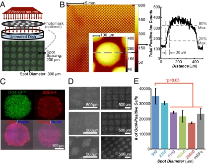
Fig. 2.
Chemical and geometrical optimized polystyrene substrates. (A) Schematic diagram of UV treatment. Treatment can be spatially controlled by inserting a photomask between the UV source and the dish. An overlay of phase-contrast and fluorescent images of transgenic Oct4-GFP hESC cultures on a UV-patterned polystyrene substrate (300-μm spot diameter with 200-μm spacing, “UV-Pattern”) is shown. UVPS was precoated with FBS. (B) ToF-SIMS scan of a UVPS surface after patterning with a photomask with a spot diameter of 300 μm with 100-μm spacing. Color indicates the intensity of all positive ions. The profile indicates a resolution of 30 μm between 20% and 80% peak changes in ion intensity. Max., maximum. (C) Pluripotency marker immunostaining of cells on UV-Pattern described in A. (D) Patterning of hESCs or hiPSCs using other geometries. (E) Number of undifferentiated Oct4-GFP–positive cells in each well after 7 d of culture as assayed by flow cytometry on the constant area patterns (15,000 cells initially seeded per well). The cumulative UV-treated area per well is the same across all patterns (details are provided in Fig. S10A). Error bars indicate 95% confidence intervals (n = 3). Surfaces were precoated with 20% (vol/vol) bovine serum, and cells were seeded in ROCK inhibitor for the first 8–12 h.

