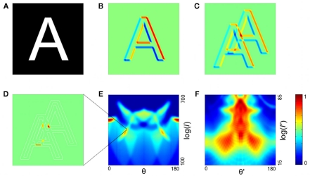
Figure 1.
The two-stage transformation. (A,B) In the first step of the first stage, edge detection is performed, illustrated for an orientation of 45° in (B) (red, positive values; blue, negative). (C,D) The second step of the transform is a spatial interval detector looking for edges separated by interval I at the same angle as the interval detector. To achieve this, the image is shifted (C), and the pixel values are multiplied, with negative values set to zero (D). (E) The image in (D) is summed over all positions to yield a single point in the log interval vs. orientation map (and similarly for other orientations and intervals; orientation range 0–180; interval range 100–700 pixels). Color code is at far right; this is linear with dark blue as zero. (F) In the second stage, the same transform is applied again, yielding a map whose coordinates are log I′ and θ′ (defined relative to the axes of the stage 1 output; interval range 15–85 pixels). Color code is at right; this is linear with dark blue as zero.

