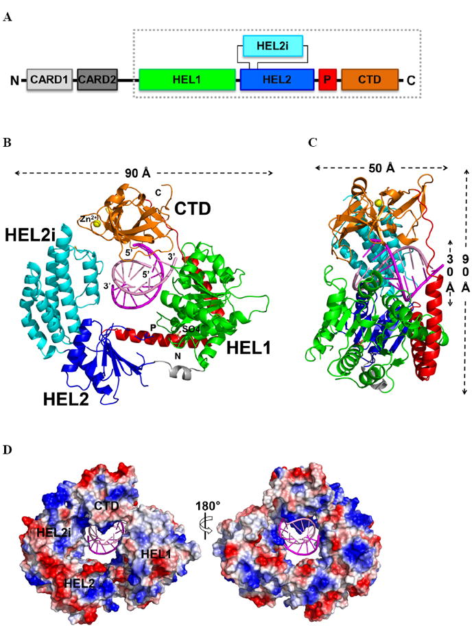
Figure 1. The RIG-I (ΔCARDs) dsRNA complex.

(A) Schematic representation of the RIG-I protein. The RIG-I (ΔCARDs) construct used for this study is boxed. (B) Overall structure of the RIG-I (ΔCARDs) dsRNA complex. Starting from the N-terminus: the helicase domain 1 (HEL1) is in green, the bridge between the two helicase domains grey, the helicase domain 2 (HEL2) blue, the insertion domain (HEL2i) cyan, the pincer region (P) red, and the C-terminal domain (CTD) orange. The top strand of the RNA duplex (dsRNA10) is in magenta and the bottom strand pink. Data collection and refinement statistics are provided in Table S1. See also the 2Fo-Fc map, shown in Fig. S1. (C) Side view showing the RNA interface with the central groove of RIG-I (ΔCARDs). A 90° rotation along the y-axis relative to the orientation shown in (B). (D) Solvent accessible electrostatic surface views of RIG-I (ΔCARDs), shown with ±10 kbT/ec. See also SAXS data provided in Fig. S3.
