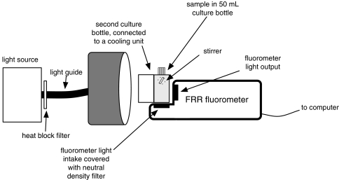
Fig. 1.
Schematic drawing of the FRRF experimental set-up. A 50-ml culture bottle contained the samples and was placed against the FRR fluorometer so that it received the flashlet sequences from behind (fluorometer light output), and the actinic light the front (i.e. the left side in this drawing). The photomultiplier detected chlorophyll fluorescence from below. Due to relatively high cell densities, neutral density filters shielded the light intake to avoid overload of the photomultiplier. A translucent cooling jacket was placed against the front of the sample to avoid rising temperatures due to heat emission from the actinic (halogen) light source. The sample was stirred with the stirrer placed at the side of the culture bottle

