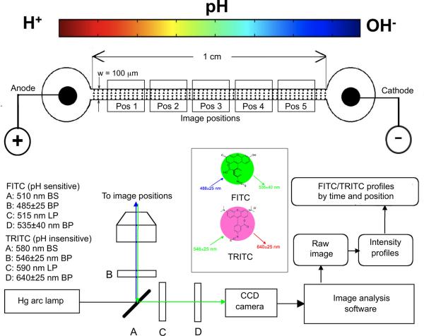
Figure 1.
iDEP microdevice schematic containing triangular posts within the 100 ⎧m wide channel spanning 1 cm between the anode/cathode wells. A fully motorized stage with position control in the x, y, and z directions was used to capture images at the specified positions 1 though 5 at specific times. Beamsplitters (BS), excitation filters, and longpass (LP) emission filters for FITC/TRITC were in a motorized turret and they are shown at A, B and C, respectively. Bandpass (BP) emissions filters were in a motorized filter wheel at D. Images were captured with a 1388×1040 resolution CCD camera, intensity profiles were obtained from unmodified images, and ratiometric analysis performed as outlined in Figure 2.

