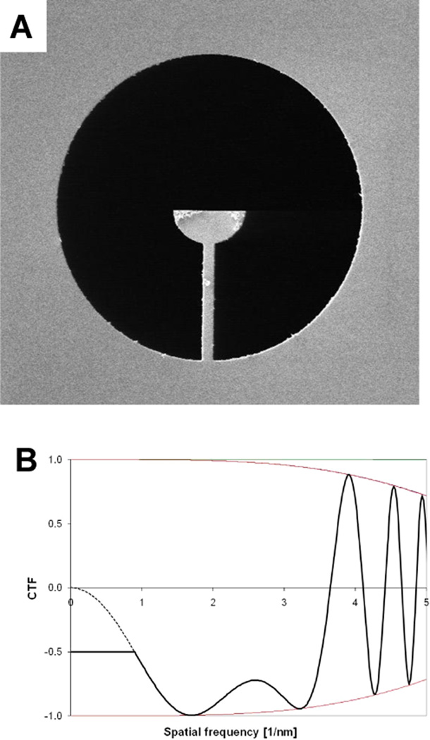
Figure 1.
Basic concept of the hybrid dsb/ssb aperture. (A) SEM image of a dsb/ssb aperture fabricated from a 1 µm-thick molybdenum foil by milling with a focused ion beam. The aperture diameter is 50 µm. When the electron-opaque half circle is positioned as closely as possible to the unscattered electron beam in an electron diffraction pattern, one half of the scattered wave will be blocked by the aperture, but only up to a scattering angle defined by the radius of the half circle. Beyond that, the device behaves as a fully open (double-sideband) aperture, apart from the unavoidable support beam that is seen in this image. (B) Comparison of CTF functions at Scherzer defocus for the hybrid dsb/ssb aperture and the usual, dsb aperture. The parameters used for this example are: electron energy = 200 keV, energy spread = 0.8 eV, Cs = Cc = 2.1mm, illumination angle = 7.5×10⁻⁶ radian, and underfocus value = 88nm (Scherzer defocus). The envelope function is mainly due to partial temporal coherence in this case, and partial spatial coherence has little effect at this value of defocus. The CTF curve for images recorded with a hybrid dsb/ssb aperture is represented by the solid line, which is constant and equal to 0.5 at low resolution, and which switches to the same curve that applies to the dsb aperture when the latter first rises to a value of 0.5. For comparison, the CTF for images recorded with a fully open (dsb) aperture is represented by a dotted curve at spatial frequencies below the radius of the opaque half-circle of the ssb device. As is explained in the text, the CTF correction needed for images recorded with a hybrid dsb/ssb aperture is mathematically different for the single-sideband region than it is for the double-sideband region.

