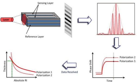
Figure 5.
Schematic of a DPI sensor chip and the interference pattern produced when light is applied onto the side of a chip. The phase shift of the fringes (TM and TE) are recorded in real time and data is resolved, where only one value of thickness and absolute refractive index at any given time-point t will satisfy Maxwell’s equations of electromagnetism for both TM and TE polarizations (adapted from [81] with permission from publisher).

