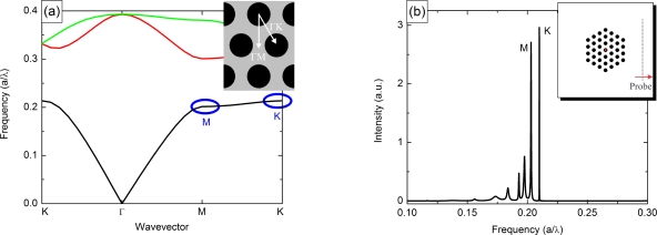
Figure 2.
(a) Calculated bandstructure of the PhC for r/a = 0.3 and npillar = 3.65 using the MIT Photonic Bands package [39,41]. The full bandgaps for TM-polarized light are clearly visible. The designed lasing points are M and K in the lowest band. (b) Predicted modes using finite-difference time-domain calculations [40]. The two lasing modes show a quality factor of 103. The inset shows a schematic of the computational cell; the source is positioned in the central pillar, the probe at the side of the cell.

