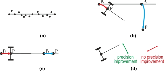
Figure 10.
(a) The straight line represents a trajectory followed by a tractor and the dots represent the positions provided by a GPS receiver placed on the tractor. (b) Trajectory of the rear axle of a tractor that turns (red) and trajectory of a GPS placed ahead of the same tractor (blue). (c) Trajectory of the rear axle of a tractor that goes straight (red) and trajectory of a GPS placed ahead of the same tractor (blue). (d) Directions with respect to the tractor orientation where the proposed method improves the positioning (green) or does not improve the positioning (red).

