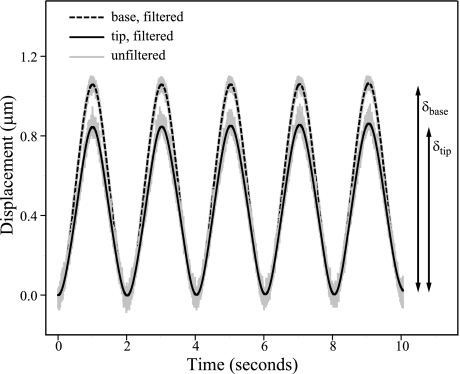
Fig. 3.
Sinusoidal displacement of bundle tip by probe. We oscillated the base of the glass fiber at 0.5 Hz, and we measured its displacement (dashed black line) with a fiber-optic sensor. We measured the displacement of the fiber tip (solid black line), which was in contact with the bundle tip, using a pair of photodiodes. The minimum of the sine wave corresponds with the resting position of the bundle and the maximum to the peak displacement in the bundle's excitatory direction. The peak-to-peak amplitude of the fiber's base (δbase) and tip (δtip) were used to calculate stiffness (Eq. 2). Unfiltered recordings of both base and tip displacements are shown in gray. The measurement shown is from a striolar hair cell located just medial to the line of polarity reversal, i.e., in zone 2 (K = 102 ± 14 μN/m).

