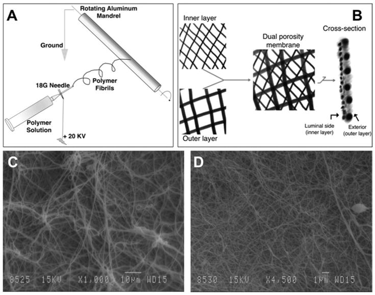
Fig 1.

(A) Schematic demonstrating the electrospinning procedure. The system beyond the tip of the 18-G needle is electrically isolated to allow fiber deposition on the rotating mandrel. (B) Schematic of the dual porosity immunoisolation membrane. The 15% nylon is first spun on the rapidly rotating mandrel followed immediately by the 40% nylon on the now slowly spinning and rapidly transplating mandrel. The cross- section schematic demonstrates the configuration in which the membrane is glued together to form a pouch. Two such mats are glued at the edges such that the inner nylon layer faces the luminal aspect. (C) Scanning electron microscope micrograph (original magnification, 1000×) showing larger fibrils and pores of the outer layer. (D) Scanning electron microscope micrograph (original magnification, 4500×) showing fine fibers and pores of the immunoisolating inner layer.
