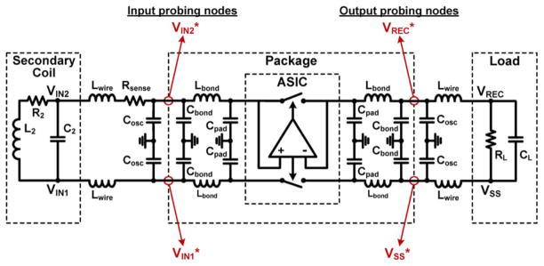
Fig. 12.
Lumped model of the circuit used in active rectifier simulations, showing capacitive and inductive parasitic components of the wire-bond and external interconnects. It is important to note that because of these parasitics, voltages measured on the coil or load, VXy, are not exactly the same as those measured on the asic package (lqfp176), VXy*.

