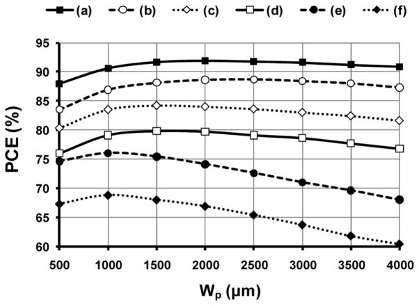
Fig. 4.
Calculated rectifier power conversion efficiency (PCE) versus Wp depending on the comparator delays when VREC = 3.2 V and RL = 500 Ω. Curve-a: TPHL = 0 ns and TPLH = 0 ns; Curve-b: TPHL = 5 ns and TPLH = 0 ns; Curve-c: TPHL = 0 ns and TPLH = 3 ns; Curve-d: TPHL = 3 ns and TPLH = 3 ns; Curve-e: TPHL = 0 ns and TPLH = 4 ns; and Curve-f: TPHL = 4 ns and TPLH = 4 ns.

