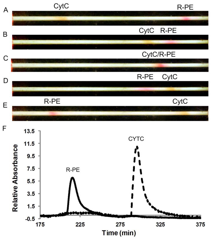
Figure 5.
Dual polarity separation of CYTC (positively charged) and R-PE (negatively charged). (A) Initial focusing conditions represented by electric field profile in Figure 3A. (B) Field is changed to move CYTC towards the inlet. (C) CYTC and R-PE passing through each other. (D) Peaks have switched positions and the field is changed to maintain the CYTC at the inlet and to capture the R-PE at the outlet. (E) Final focusing conditions prior to eluting both peaks past the detector. (F) Electropherogram for the dual polarity separation with the CYTC and R-PE switched.

